Fitting a LiFePo4 battery to a Bailey Pheonix caravan
Part #18 of the "Roger Writes" series - June 2025
Background
We use a lot of power in our caravan, TV + Media PC, Laptop, 4G, changing phones/tablets, as well as the usual pumps and fans.
We have 150W of solar on the roof, and for longer events, I plugged in an extra battery or two, but over time, even with 3 batteries, it was struggling.
It was time to upgrade, and LiFePo4 was the obvious choice.
Measuring up
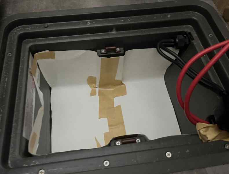
In a caravan space is a premium, so I really want to see what I could fit in the existing battery tray (which is under the floor in this Bailey).
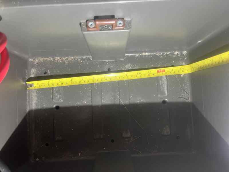
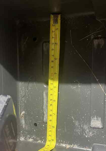
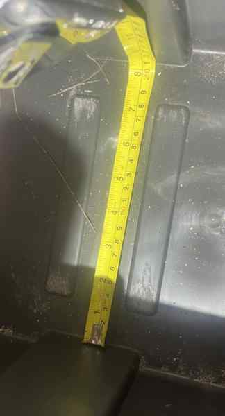
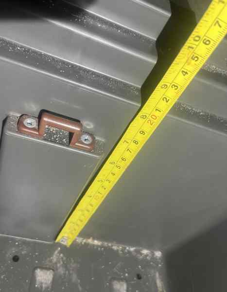
After measuring up, I made a 3D template (Cardboard aided design)
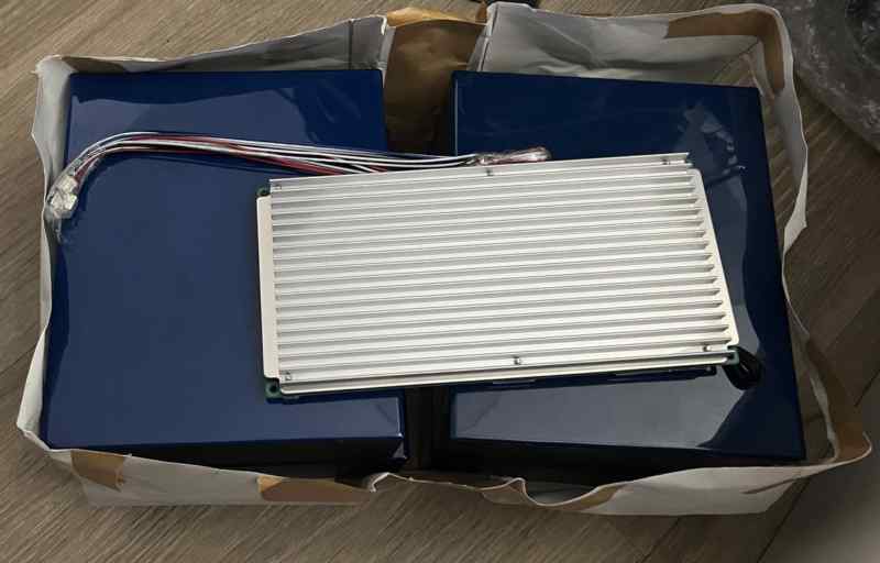
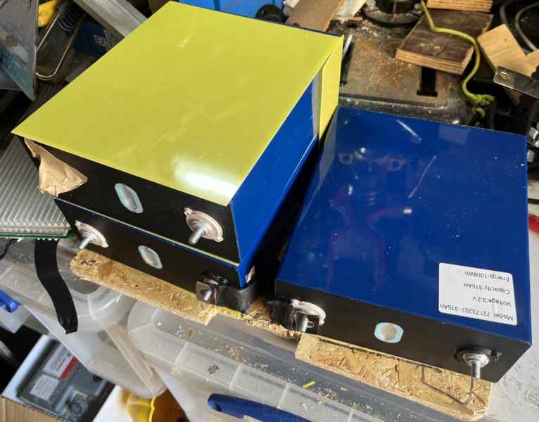
Using this, I experimented with several different battery sizes, and configurations. I worked out that 4x 315Ah cells would "just about" fit. It's really tight!
So (in November 2024) I ordered 4x 315Ah B-Grade cells, and a 300A 4S BMS, for a total of £269.95 (from Fogstar batteries).
Because the caravan is not at home, when they arrived, I did a test fit (in the CAD model):
When I was next a the caravan, I did a test fit in the actual battery tray:
It fitted - Phew!!
Battery tray
LiFePo4 contains a phenomenal amount of energy, so you don't want things moving around and shorting out.
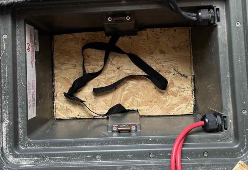
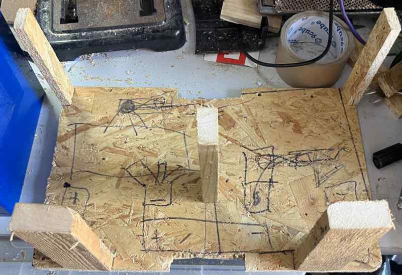
To keep things secure, I started with a base plate:
Then built up the layers:
Added a top support, and started mocking up the negative connections (from 12.5mm x 1.5mm copper):
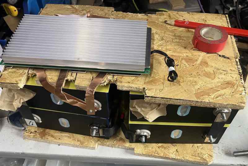
The cells need some side pressure to stop them swelling, so added some verticals to pull the top and bottom panels together:
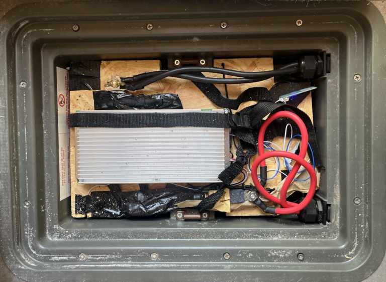
Reassembled, added the balance leads, and the fuse:
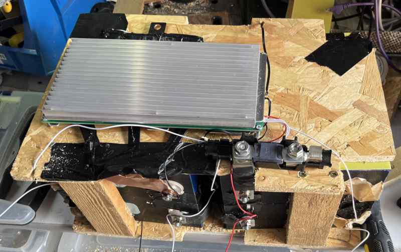
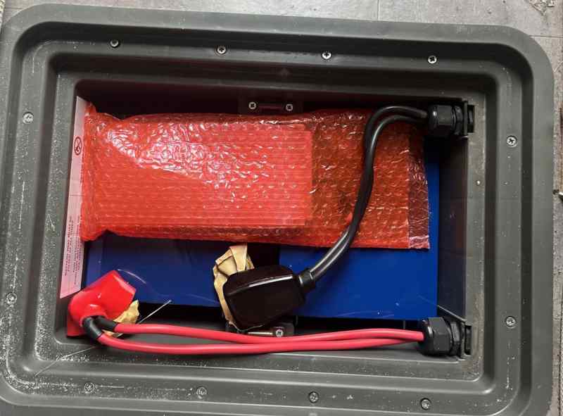
Then did the final fit:
Initial charge and discharge
It's recommended to fully charge to 100% and discharge the battery to it's cut off point, before first use.
(Some people suggest to put the cells vertical for the first charge / discharge, so I turned it on it side. Not sure it helps, but was easy to do, so why not?)
The battery was already part charged, and at between 10A & 20A it took over 24 hours to fully charge, taking just over 3000Wh.
I used a trailer lighting board (all bulbs wired to on) to fully discharge it, this drew around 7A for 45 hours, using a total of 4100Wh!
During the discharge I recorded the battery voltage every hour or so. I used these values to better estimate the 10%, 20%, 30%, .... 90% voltage levels in the BMS, so that it's remaining capacity value is more accurate.
To prolong the life of the battery I decreased the maximum voltage, and increased the minimum voltage. I estimate this will give 3500Wh usable capacity.
Compared to the lead-acid, this weighs 5kg more but is around 7x the usable capacity!
Making the charging LiFePo4 compatible
To fully charge a LiFePo4 battery you need a slightly higher voltage (usually 14.6V) copmpared to Lead-Acid (usually 13.8V) / AGM (usually 14.4V). Also a flat LiFePo4 battery will draw as much current as is available, so you need to limit the current, otherwise it will pop the fuses in the charging path.
In this caravan, there are 3 source of charging:
- Solar - from a 150W panel on the roof, via an MPPT controller
- Car - via the 13-pin towing cable
- 240V (EHU) - via the 20A power supply in the Bailey power unit
Solar charging
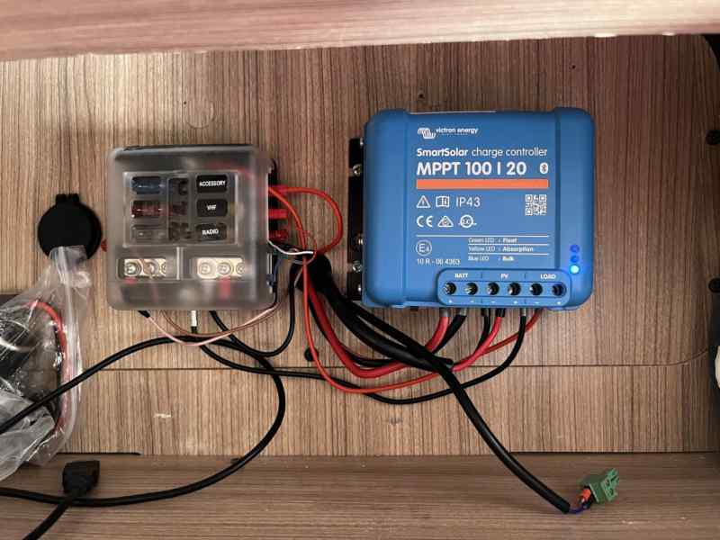
This was easy, I just swapped the old (lead-acid/AGM only) MPPT for one that has a LiFePo4 profile.
(If you use the Victron controllers watch out as the Battery connection is the other way around to the other two, with the +ve on the left/-ve on the right!).
Car charging
To fully charge a LiFePo4 battery from the car, the voltage needs boosting.
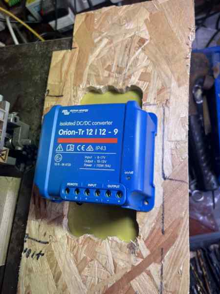
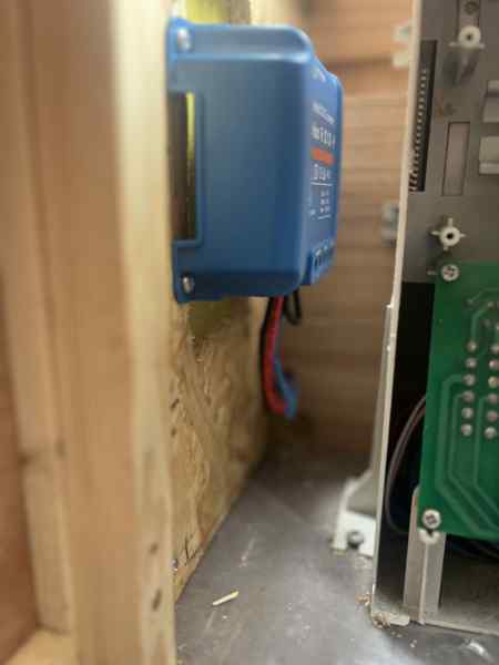
I decided to use a 9A DC:DC converter, this will boost whatever comes from the car to the 14.6V needed to fully charge the battery, it will also limit the current drawn from the 13-pin (which is usually fused at 15A).
This was mounted on a board with a cutout to allow some extra air flow, with a heatproof backing board behind that:
The 13-pin trailer connection has 2 separate high current circuits, one is for the caravan power and battery charging (pin 9 +ve/13 Gnd) this is always on. The other can power the fridge (pin 10 +ve/11 Gnd). The fridge circuit is usually only powered when the ignition is on / engine is running, it is also used to switch the pin9/pin13 circuit between just powering the caravan, and charging the battery.
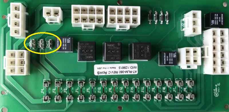
By tracing the operation of the relays on the controller board, I could see that the CHG1/CHG2 connections could do most of what I needed.
- CHG1 is connected via a fuse to the battery
- CHG2 is connected to the main caravan circuits (via relays)
- The power feed from the mains (EHU) charger/power-supply is connected to CHG1, a link wire connects CHG2 to CHG1

13-pin 9/13
(Always-on) | 13-pin 10/11
(Fridge) | Mode | Circuit board relay(s) connecting
CHG2 to Caravan circuits | CHG1/CHG2 | Note
|
|---|
| off | off | Car disconnected | Switched by panel master switch | CHG1 powers CHG2 | Normal operation
|
| on | off | Car powers the caravan | Off | CHG2 isolated | Car powers the caravan - doesn't charge the battery
|
| on | on | Car powers and charges the caravan | On | CHG2 powers CHG1 | Battery charging from 13-pin 9/13
|
From this table, we can see that in normal operation, CHG1 needs to be connected to CHG2, but to charge, the DC:DC converter needs to inserted beween CHG2 and CHG1 (powered from CHG2, powers CHG1). This can be done with a changeover relay between CHG2 and CHG1.
- Relay common (terminal 30) goes to CHG2.
- Relay NC (terminal 87A) goes to CHG1. This uses a piggy back connector to connect the relay NC and the DC:DC power out (blue cable) into the connector that was on CHG2 (that used to join CHG1/2 and still goes to CHG1).
- Relay NO (terminal 87) goes to the DC:DC power in (red cable to DC:DC).
- Relay coil is powered from the fridge circuit (13-pin pins 10/11)
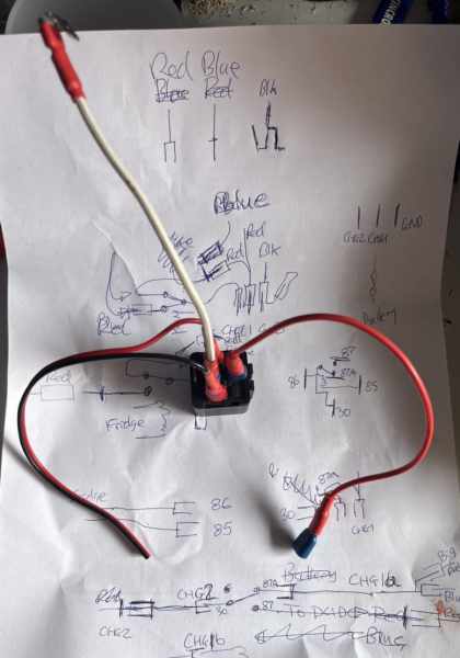
This is it wired in, with three wires going to the DC:DC converter:
- Black= -ve (piggy back connector on the GND)
- Red= DC:DC in (relay terminal 87)
- Blue=DC:DC out (link wire to CHG1 + white wire to relay terminal 87A)
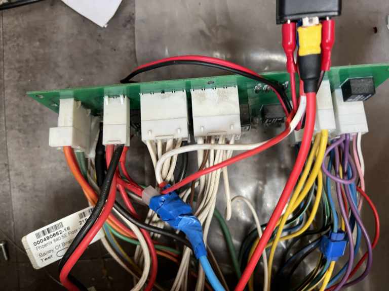
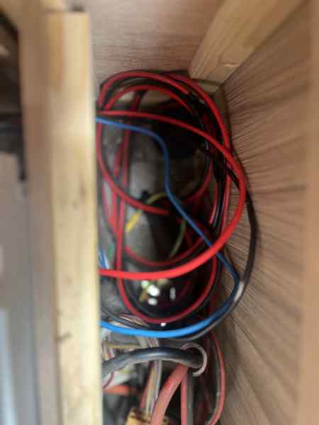
The three wires to the DC:DC were routed to the left of the fuse box.
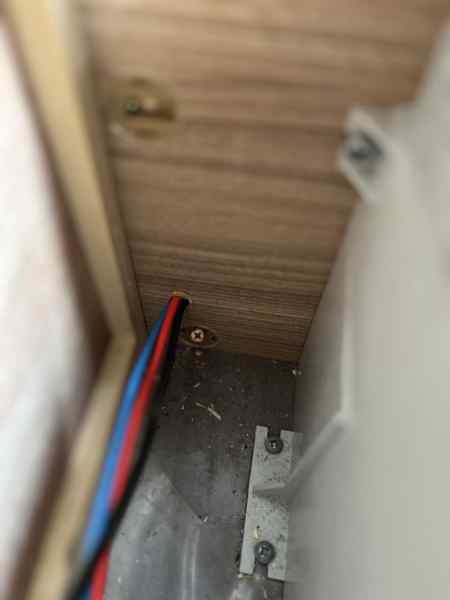
Where I want to mount the DC:DC module, it's difficult to get to the mounting screws, so screwed it to the backing board, sorted out the wiring (Black to the -ve in and -ve out, Red to the +ve in, Blue to the +ve out), then mounted the backing board.
The spare cable, was pulled back into the space behind the fuse box:
240V AC (EHU) charging
I was planning to insert a DC:DC unit between the mains Power Supply Unit (PSU) and the PCB to boost the voltage, and limit the charge current.
The PSU specification (it's labelled PO120 / PS276-1-BC, and the datasheet can be found by searching for that) shows that it has voltage and current limiting built in, with a maximum of 14.4V or 20A. Although the 14.4V won't fully charge the LiFePo4 battery it will get it to around 85%. The 20A limit is a fraction of the max charge current (315A) so that's fine.
Adding a DC:DC in this path is pretty complex, it would require the caravan power and the battery feed to be split. This would probably require cutting tracks on the controller PCB, and would only increase the possible charge a little. 85% of 315Ah is 268Ah, that is nearly 5x the usable capacity of the 110Ah lead-acid, on EHU that last 15% isn't really required!
Next steps
Heater
Athough LiFePo4 batteries can supply power down to -25C, they shouldn't be charged below 0C. So at the end of the season (before the depths of winter) I'll add some battery heater plates between the cells, this will keep them above 0C, so the solar can safely charge them
The BMS has a heater connection, but it's not documented, so some experimentation might be required!
Monitoring
The caravan has a 4G connection via a Teltonika router that runs a modified version of OpenWRT. This would allow a USB connection from the router to the BMS to log the battery temperatures/voltages, and remotely report them. But, it looks like the BMS battery remaining status is just voltage based, not coulomb counting, so I might add a current shunt. If this is Victron then the same USB device could monitor the Solar as well.
The Roger Writes series
I research / dabble with lots of things, and figured that if I write my notes here, I can quickly reference them, also, sometimes, they are useful to others!
Here is what I have so far:
Homepage.
This page was lasted updated on Wednesday, 30-Jul-2025 14:14:51 BST

This content comes from a hidden element on this page.
The inline option preserves bound JavaScript events and changes, and it puts the content back where it came from when it is closed.
Click me, it will be preserved!
If you try to open a new Colorbox while it is already open, it will update itself with the new content.
Updating Content Example:
Click here to load new content